Introduction to Fuel Cells
Our modern society depends on electricity. There are many ways to generate electricity via fossil fuels, hydroelectric dams, wind turbines, and solar cells. Among them, burning fossil fuels, such as petroleum, coal and natural gas, still remains as one of the dominant sources of electricity where the heat is converted into electricity with a heat engine. As we will learn in Module 3, such heat engines are often fairly inefficient (around 30% heat to electrical work). They are also difficult to scale down: for example, it is nontrivial for one to create a small and efficient natural gas heat engine to power a computer.
An alternative to convert fuel to electricity is a fuel cell. Fuel cells work by allowing hydrogen or methane (i.e., natural gas) to react with oxygen to form water or carbon dioxide. This process directly generates electricity, whereas the heat engine converts heat into mechanical work, and mechanical work is then converted into electricity. A fuel cell can achieve nearly 70% energy conversion efficiency, which is much better than that of a heat engine. The increase in conversion efficiency not only reduces fuel consumption but also minimizes the release of harmful greenhouse gases. Furthermore, fuel cells are scalable where they can be used to power a device as small as an integrated circuit chip, or as large as a city.
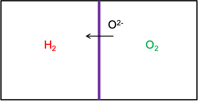
To understand fuel cells, let’s consider mixing at ambient pressure two reacting gases, such as hydrogen and oxygen, in a chamber. If we ignite the mixture, the fuel mixture will combust and release heat. However, such thermal energy cannot be converted into work unless coupled to a heat engine. Next, let’s consider what would happen if we separate the hydrogen and oxygen gases into separate chambers. For simplicity, let’s assume the two chambers are separated by a membrane that only allow oxygen ions to pass through both ways, but not electrons or charge-neutral hydrogen or hydrogen ions (See Figure 2.1.1).

Figure 2.1.1:Fuel cell schematic where the membrane only allows oxygen ions to pass through
As shown in Figure 2.1.1, with the help of catalysts, some oxygen gas molecules will dissociate into oxygen ions and pass through the membrane to react with hydrogen. This chemical reaction at the anode (H2 chamber) can be expresed as Equation 2.1.1
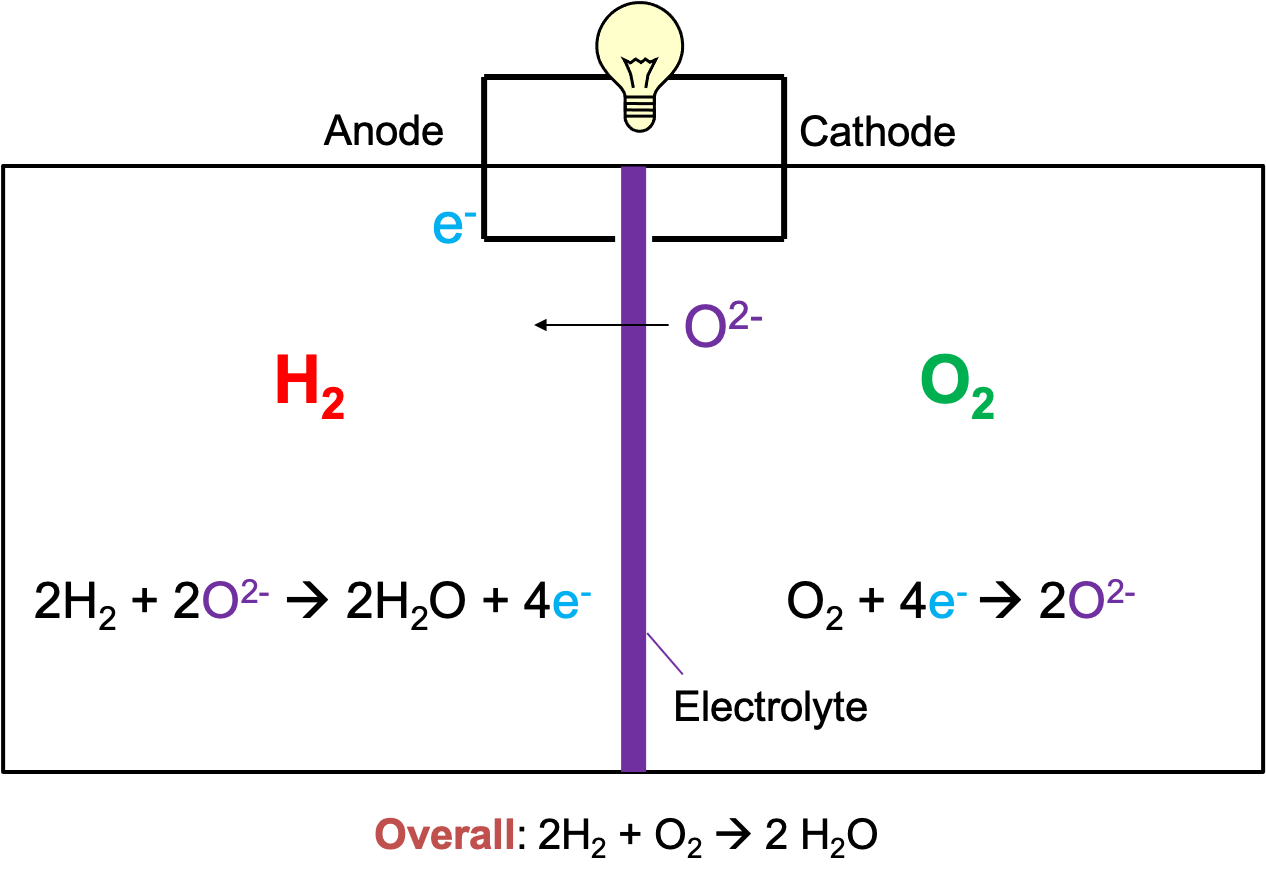
To extract elecrical work, we need to connect the anode with the cathode (O2 chamber) to allow electrons to flow (i.e., electrical current), as seen in Figure 2.1.2. The excess electrons will then combine with the oxygen gas to form oxygen ions, completing the reaction loop. The chemical reaction at the cathode can be expressed as Equation 2.1.2.

Figure 2.1.2:A functional fuel cell with a light bulb powered by the complete circuit
Equation 2.1.1 and Equation 2.1.2 are two half reactions that can be combined into a net reaction as seen in Equation 2.1.3.
The difference in the chemical potentials of oxygen and hydrogen species give rise a voltage across the cathode and the anode, which we will go into more details in later sections.

