Tilt-Corrected Bright-Field STEM
Principle of Reciprocity
In Bloch Wave Algorithm, we used the fact that off-axis pixels inside the BF disk are equivalent to tilted plane waves to calculate CBED patterns. Formally, this relationship is referred to as the principle of reciprocity, which states that rays connecting a source to a detector follow he same optical path as the rays from the detector to the source Krause & Rosenauer, 2017.
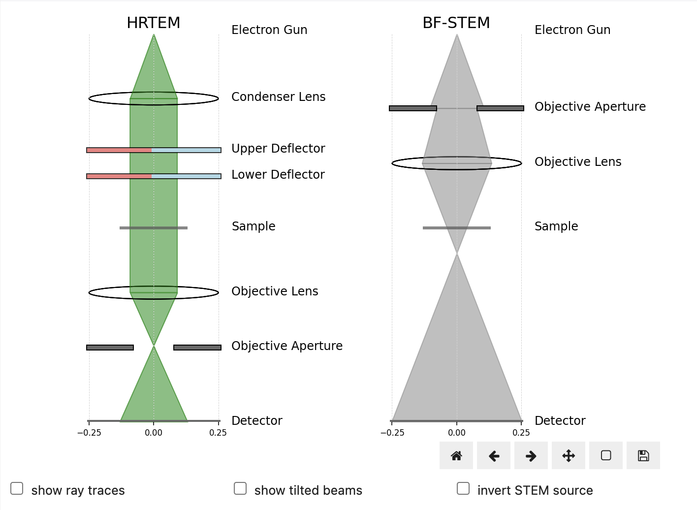
Figure 11.1 shows how this can be used to show that tilted HRTEM images are equivalent to virtual images created using off-axis pixels in BF-STEM. By following the tilted rays from source-to-detector in HRTEM and detector-to-source in STEM we can see reciprocity in action. Notice how the tilted rays impact the sample at different positions, giving rise to the apparent lateral image shifts.
Lateral Image Shifts
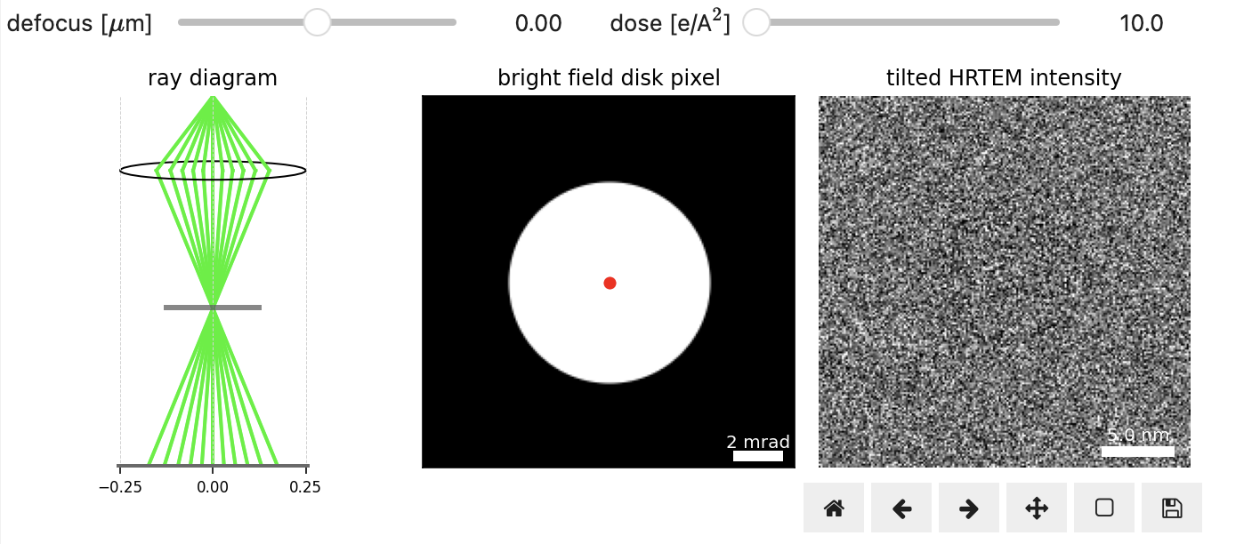
Consider the virtual BF image formed by integrating only the center-most pixel of the bright field disk in a 4D-STEM experiment in Figure 11.2. This image is analogous to a conventional HRTEM image at the same conditions. More generally in STEM imaging, as the collection angle is decreased, diffraction contrast increases, and the resulting image looks more like a HRTEM bright field image Springer International Publishing, 2016. Recall that, as we saw in Phase Problem in Electron Microscopy, we can increase the contrast by introducing defocus.
When defocused, tilted planewave illumination (equivalent to off-axis virtual BF-STEM images) produces lateral image shifts. This can be seen by clicking on the BF-disk in Figure 11.2. The magnitude of the shifts increases with increasing defocus, which is based on the geometry of a defocused probe, as illustrated on the left.
Aberration Surface Gradient
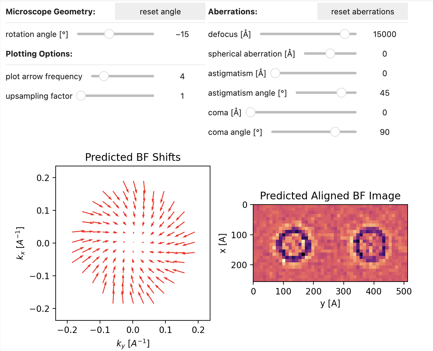
More generally, the lateral shifts are given by the gradient of the aberration surface LUPINI et al., 2016:
Figure 11.3 investigates the effect of common aberrations and microscope geometry variations, away from the ground-truth values (relative rotation angle = -15°, and defocus = 1.5μm), on the apparent image shifts of virtual BF images and the aligned virtual BF stack.
- Krause, F. F., & Rosenauer, A. (2017). Reciprocity relations in transmission electron microscopy: A rigorous derivation. Micron, 92, 1–5. 10.1016/j.micron.2016.09.007
- Transmission Electron Microscopy. (2016). Springer International Publishing. 10.1007/978-3-319-26651-0
- LUPINI, A. R., CHI, M., & JESSE, S. (2016). Rapid aberration measurement with pixelated detectors. Journal of Microscopy, 263(1), 43–50. 10.1111/jmi.12372


