Direct Ptychography
Electron ptychography, first proposed by Walter Hoppe in 1969 Hoppe, 1969, is a powerful phase-retrieval technique which can achieve resolution beyond the “information limit” Nellist et al., 1995. Ptychographic methods are usually grouped in “direct” methods, which include single side band (SSB), and Wigner distribution deconvolution (WDD), which attempt to deconvolve the effects of the probe from the 4D-STEM dataset, and iterative model-based inversion methods. We focus on the former in this section, and describe iterative methods in Iterative Ptychography.
Single Side Band Ptychography
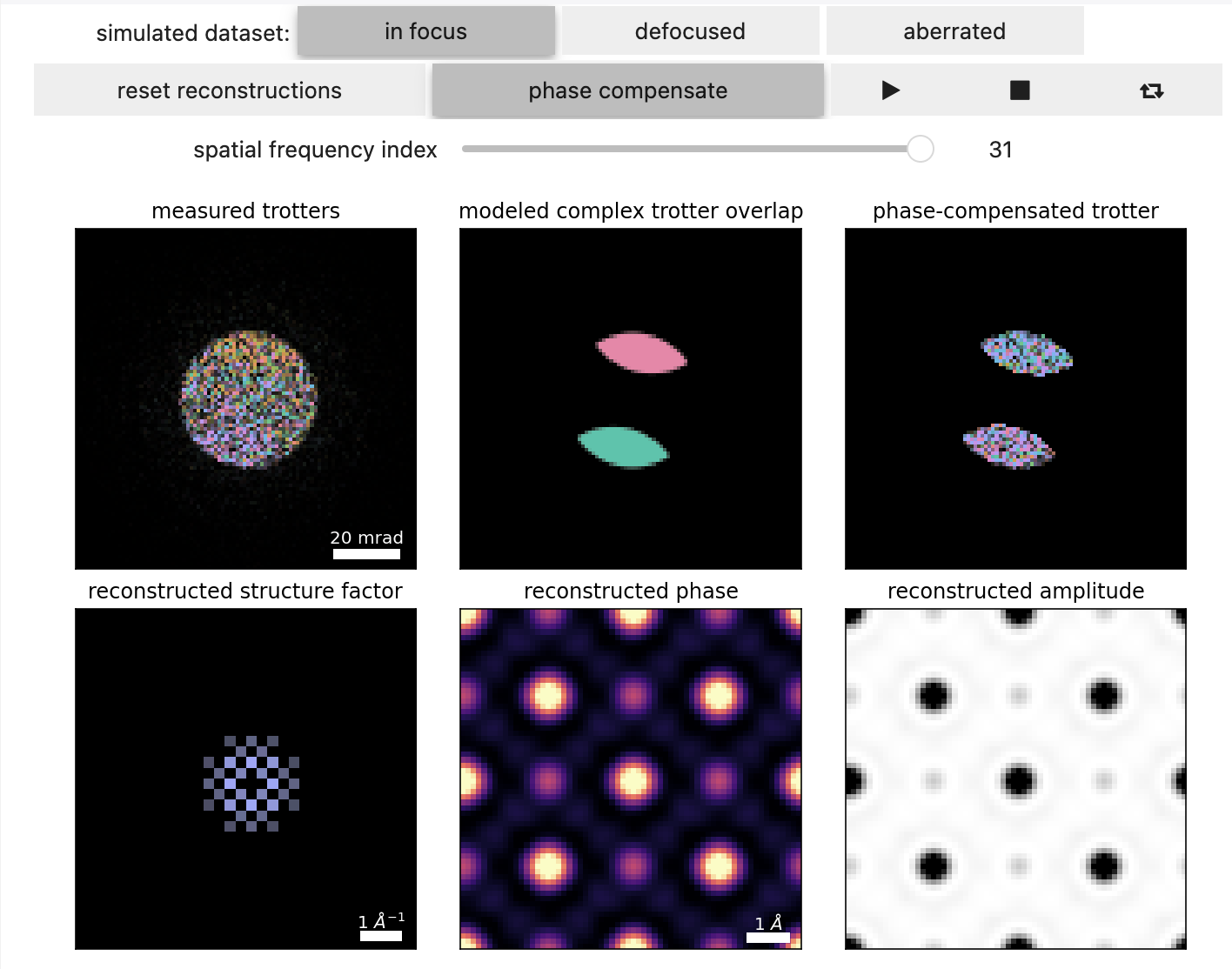
The first step in direct ptychographic methods is taking a Fourier transform over the real-space scan positions to form the complex-valued dataset . This is shown in Figure 12.1, and holds a wealth of information:
- The amplitude arises from the overlap between the bright-field aperture and two apertures centered at .
- At high spatial frequencies, this forms two regions of “double overlap”
- At low spatial frequencies, the “double-overlap” regions can themselves overlap, leading to the “triple-overlap” region
- At zero-defocus, the “triple-overlap” region cancels out and holds no information
- The similarity of the low-spatial frequency probe overlap regions to Pig's trotter, gave rise to the colloquialism we wiill adopt
- Importantly, note that the phase of each “trotter” is constant (for zero-defocus)
- The relative rotation of the dataset (here -15°), can also be visualized
Probe Deconvolution and Aberrations
If we know our convergence semiangle accurately, and have calibrated the relative rotation, we can deconvolve the effects of the probe, by making a mask using one of the two trotters, and summing the (near-constant) phase inside them. We assign that phase to the structure factor at that spatial frequency, and inverse Fourier transform the structure factor to obtain our reconstructed object.
In the presence of residual probe aberrations, the SSB technique we outlined above breaks down since the phase inside each trotter is no-longer constant Pennycook et al., 2015. To account for this, one can use a complex-valued filter to compensate the phase variation inside the trotters Ophus et al., 2016.
Aberrations Fitting
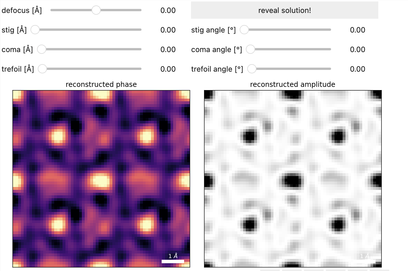
The phase-compensation technique above works really well for known aberrations. Often times however, we need a robust estimate of residual aberrations in our probe. The same phase-compensation can be formulated as a linear system of equations and fit aberrations up to a given order in the least-squares sense Yang et al., 2016.
Figure 12.2 highlights the delicate manner by which aberrations enter the SSB reconstruction. Try playing around with the sliders to see if you can recover the residual aberrations by optimizing the reconstruction.
- Hoppe, W. (1969). Beugung im inhomogenen Primärstrahlwellenfeld. I. Prinzip einer Phasenmessung von Elektronenbeungungsinterferenzen. Acta Crystallographica Section A, 25(4), 495–501. 10.1107/s0567739469001045
- Nellist, P. D., McCallum, B. C., & Rodenburg, J. M. (1995). Resolution beyond the “information limit” in transmission electron microscopy. Nature, 374(6523), 630–632. 10.1038/374630a0
- Pennycook, T. J., Lupini, A. R., Yang, H., Murfitt, M. F., Jones, L., & Nellist, P. D. (2015). Efficient phase contrast imaging in STEM using a pixelated detector. Part 1: Experimental demonstration at atomic resolution. Ultramicroscopy, 151, 160–167. 10.1016/j.ultramic.2014.09.013
- Ophus, C., Ciston, J., Pierce, J., Harvey, T. R., Chess, J., McMorran, B. J., Czarnik, C., Rose, H. H., & Ercius, P. (2016). Efficient linear phase contrast in scanning transmission electron microscopy with matched illumination and detector interferometry. Nature Communications, 7(1). 10.1038/ncomms10719
- Yang, H., Rutte, R. N., Jones, L., Simson, M., Sagawa, R., Ryll, H., Huth, M., Pennycook, T. J., Green, M. L. H., Soltau, H., Kondo, Y., Davis, B. G., & Nellist, P. D. (2016). Simultaneous atomic-resolution electron ptychography and Z-contrast imaging of light and heavy elements in complex nanostructures. Nature Communications, 7(1). 10.1038/ncomms12532


